lab08 : Basics of electronics with Raspberry Pi, by Diba
| num | ready? | description | assigned | due |
|---|---|---|---|---|
| lab08 | true | Basics of electronics with Raspberry Pi, by Diba | Wed 08/17 09:30AM | Fri 08/19 03:45PM |
If you find typos or problems with the lab instructions, please report them on Piazza
Learning objectives
In this lab you will be introduced to the basics of electronics using a a credit-card sized computer called the Raspberry Pi (yummy!). You will build simple electronic circuits and write programs to control them.
Getting started
Create a git repo and get the starter code
Use your laptop to create a new repo called spis16-lab08-Name-Name using Method 1. When creating the repo import the starter code from this git repo: https://github.com/ucsd-cse-spis-2016/lab08-startercode.git
You may also also create just an empty repo with a .ignore and README just like you have in the previous labs and then copy over starter code as per instructions in the later part of this lab
Note that you must keep your git repo updated with the latest version of your code because your code will be erased from the Pi at the end of the lab session. This is to ensure that the hardware is ready for use by the next group.
Observe your Raspberry Pi
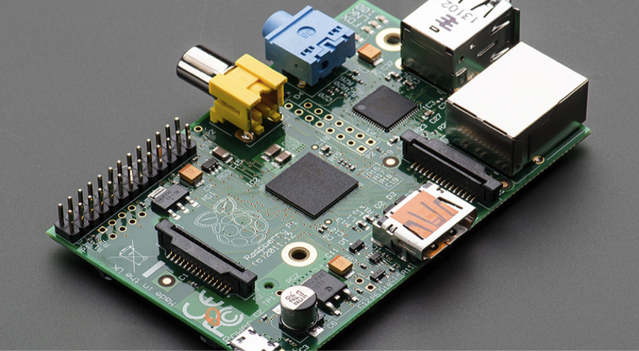
Take a look at the Raspberry Pi on your workbench. You are looking at the insides of a computer. The Pi is not shy about exposing its true self. You would see a similar circuit if you cracked open the shiny shell of your laptop (which is probably not a great idea to quench your curiosity). As you stare down at your Pi, you see an all-encompassing circuit. Your gut feeling may be that it all looks very complex. Your premonitions are not misplaced. The circuit that you are looking at is not called the motherboard for nothing!
The green base on which all the electronic components (which you see as bulgy entities) are laid out is a non-conductive substrate. This means that the green parts of the board don’t conduct electricity. However, to connect the various electrical components, conductive tracks made of copper are etched on the green base. At the very center of your Pi sits a prominent black square block. This is the brain of your Pi – the processor. But the processor is not the only thing on the black square. It is clubbed with some Random Access Memory (RAM). For now, just know that the RAM is a form of non-persistent memory. There are other components on the Pi. To identify them orient your Pi to match the circuit below.
A corresponding functional diagram of the Pi is also shown below:
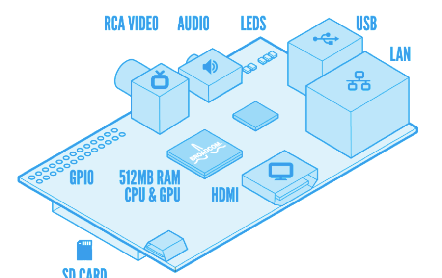
Observe the components marked in the diagram (above) on your Pi. We will focus on a few important components on the diagram:
-
Ethernet port: The Pi can get Internet connectivity through the Ethernet port, marked as LAN or through a WiFi dongle connected to one of its USB ports. In our setup, we will use the WiFi.
-
High Definition Multimedia Interface (HDMI): This is an interface that connects your Pi to a monitor.
-
SD card slot: All the software that runs on the Pi, which includes the Operating System (more on the OS later) as well as your programs, will be stored on the SD card that goes into the SD card slot. The Pi without the SD card is all hardware.
-
GPIO pins: This stands for General Purpose Input / Output. You won’t be able to observe the GPIO pins on the Raspberry Pi on your workbench because they are hidden under the gray/black ribbon cable that connects them to the white breadboard. These pins can be configured to send/receive signals through your python programs. You will control and sense the world around you through these pins!!
-
Power Input: Using this input you can power up your Pi using a charger or a batteries.
Observe the connections from your Pi to other peripherals
In the setup provided to you, the Pi has been wired to work as a desktop computer! Actually its more than a desktop because it is setup to connect to an electronic circuit that you will soon create (something you can’t do with standard desktops) Next week we will operate the Pi in a untethered fashion (as a mobile robot) but for now observe the following wired connections from the Pi to other peripherals:
- The Pi has a connection to a monitor via the HDMI port.
- The keyboard and mouse are connected to the in-built USB hub of your monitor. A single USB cable from the monitor connects the keyboard and mouse to the Pi.
- The Pi is powered up using a charger that is plugged into the wall.
- The GPIO pins on the Pi are routed to a breadboard via a black ribbon cable.
Let’s take a closer look at the breadboard and the GPIO breakout board that sits on it. You will need this information to complete the later exercises in this lab
The breadboard
The RPi chip itself is very small, so we will be attaching an electronic component called a breadboard – which is designed to make it possible to experiment with circuits by extending the available space. For electricity to flow you need connections. Think of a breadboard as a way of giving you more space to make those connections. The main feature of the breadboard is that it comes with a set of in-built electrical connections which significantly simplifies the wiring involved in complicated circuits. Let’s try to understand the electrical connections on the breadboard using the figures below:
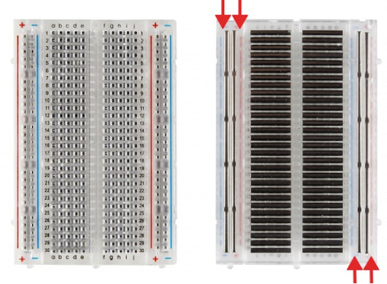
The figure on the left shows a picture of the breadboard as visible to you, while the one on the right shows in internal electrical connections when the back of the breadboard is uncovered. The rows are numbered 1 through 30 and the columns ‘a’ through ‘j’. In the figure on the right observe how the conductive metal strips run across the rows. This means that any two grids that are on columns ‘a’ through ‘e’ are at the same potential as long as they are also on the same row. Similarly, any two grids that are on columns ‘f’ through ‘j’ are at the same potential as long as they are also on the same row. However, the two halves of a row are electronically disconnected. As you will see, this helps you out a lot!
Are each of the following grids internally connected on the above shown breadboard?
- a1 and a2
- a1 and b2
- a1 and b1
- c14 and f14
- j1 and j2
- a1 and e1
Finally, the breadboard has two vertical lines running up and down on both sides. The pins on each of these lines are electrically connected but the lines are electrically disconnected from each other. The convention is to connect a positive voltage to the line that has a ‘+’ sign above it and connect the ‘ground’ to the line with the ‘-‘ sign above it.
The GPIO pin numbering conventions
The Raspberry Pi 1, model B (which is the one we are using) has 26 GPIO pins that are laid out as two rows of 13 pins each, also depicted in the diagram below:
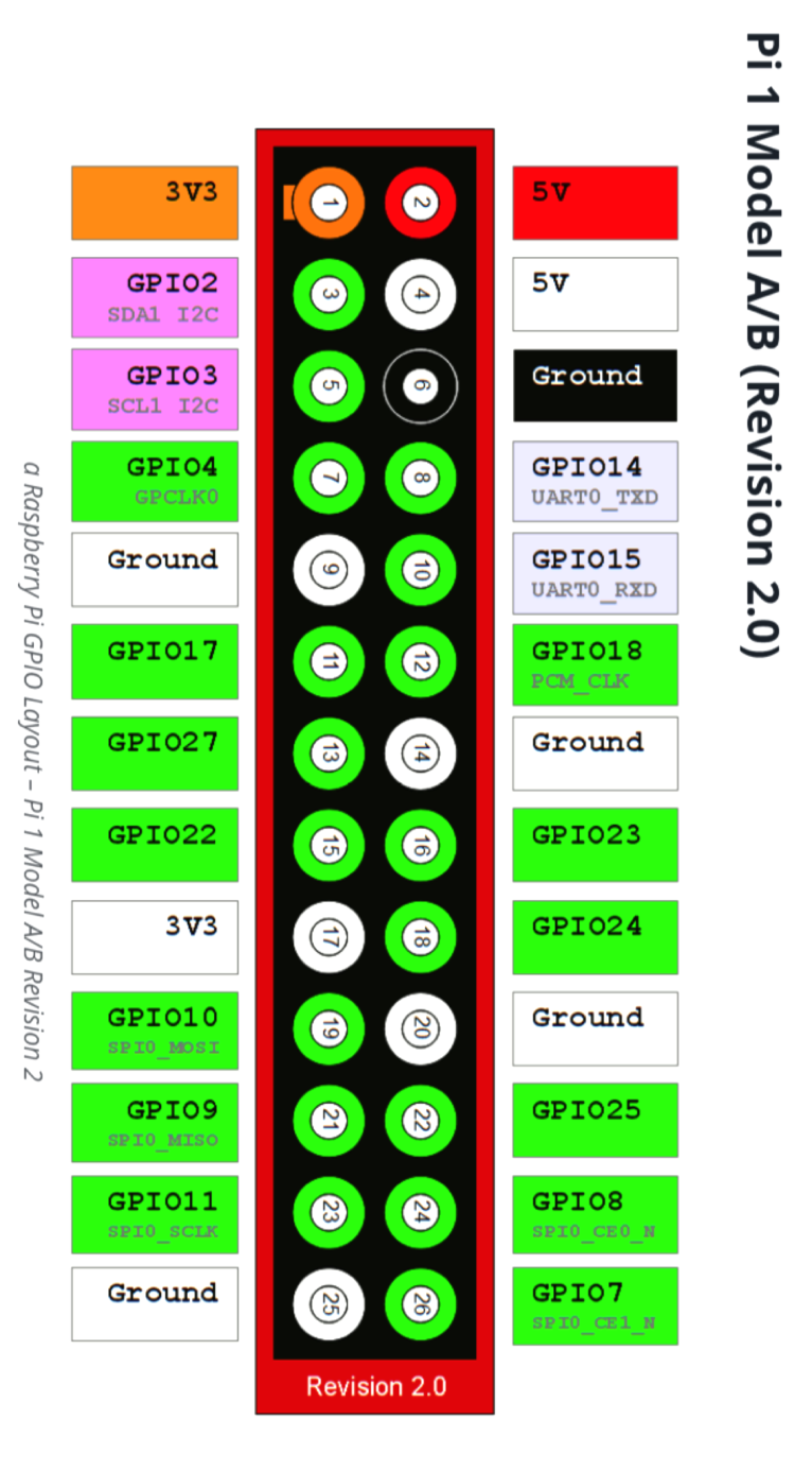
The pins that are colored in green are available for any general purpose and can be referred to and configured in your python programs! There are two different conventions used to refer to these pins:
-
Physical location: One way is to just refer to the pins based on their physical location. These numbers are indicated in the circles (representing the pins) in the above diagram. All pins on the left half have odd number locations while all pins on the right half have even numbered locations.
-
BRCM (broadcom convention): You can also use the broadcomm convention where the numbering is not based on the physical location. For example the pin at physical location 12 is referred to as pin number 18 as per the BRCM convention.
Either of the above conventions is okay to use in your programs as long as you define which scheme you are using before you start referring to the pins.
Note that physical pins 1 and 17 provide 3.3V, while physical pins 2 and 4 provide 5V. Physical pins 6, 9, 14, 20 and 25 provide the ground signal which is also very important in your circuits. We will talk about pins 3, 5, 8 and 10 in later labs.
The GPIO breakout board shown below makes all these pins available to you on a breadboard where you will be doing your electrical wiring.
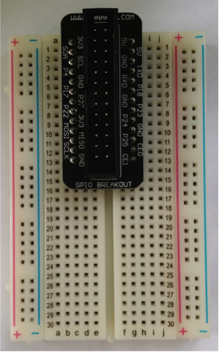
Notice that the labels on the breakout board use the BRCM naming convention. However, we have connected the breakout board in such a way that you can easily derive the physical pin number of any pin by looking at the row number that it is connected to on the breadboard. Answer the following questions based on your understanding of the breadboard and the GPIO numbering scheme:
- What is the physical number for a pin on the left half of the breadboard on the nth row number, for any ‘n’?
- What is the physical number for a pin on the right half of the breadboard on the nth row number, for any ‘n’?
Getting to know your desktop environment
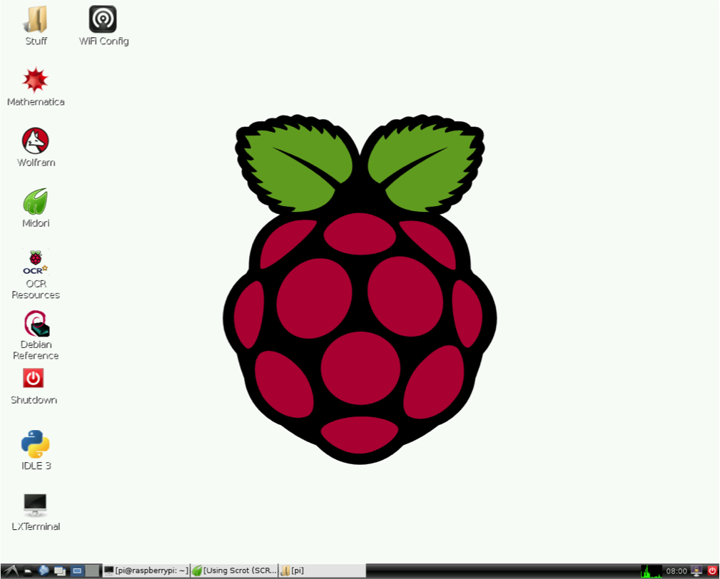
The operating system on the Pi is a version of the linux known as Raspbian. The picture above shows the Raspbian desktop environment. Like Windows, or OS X (for Apple), you can run programs by double clicking them. Feel free to poke around and see what all of these icons mean! We will use two main programs on your desktop: the Wifi config tool and the LXTerminal.
The WiFi config tool
This tool shows the status of your Wifi connection and internet connectivity. Use the mouse navigate to the WiFi Config Tool on your desktop. Double click on it to view the status of your network connection. Take note of the IP address in the GUI of that tool. Your IP address is of the form: 137.110.XX.XX. If you see such a number then you have internet connectivity. You can use the IP to remotely access your Pi from any other computer using ssh (just like how you log into the ieng6 machines, more on this later)
LXTerminal
LXTerminal is the command line interpreter. Double click on the icon to open it.
When you open LXTerminal notice the prompt says pi@spispi-XX. This means that you are user pi and the name of your machine is spispi-XX.
All the unix commands that you have learned so far can be used to navigate through the file system on your Pi. You can also use command line git just like how you would on the ieng6 machines!
Setup your programming environment
- Configure your git credentials on the Pi. In the home directory
/home/pitype the following commands replacing my name and email credentials with yours.
 git config --global user.name "Diba Mirza"
 git config --global user.email dimirza@eng.ucsd.edu
- Clone your git repo over https into your home directory on the Pi. DO NOT log into the ieng6 machines and try to do this step there. To clone your repo first open a browser on your laptop (not the Pi) and navigate to your repo on github which should be called
spis16-lab08-Name-Name. Go to the green button that says ‘clone or download’ and get the https address of your repo. The https address should be something likehttps://github.com/ucsd-cse-spis-2016/spis16-lab08-Name-Name.git. Do not use the ssh address as you have in the past.
Make sure you have the starter code which are the files 01_blinking_led.py and 02_buttonLED.py in your repo. If you did not import the starter code when creating the repo, you can copy it over from the directory /home/pi/lab08-startercode/ on the Pi
To do this type the following command replacing the second argument by the name of your repo
cp ~/lab08-startercode/*.py ~/spis16-lab08-Name-Name/
On the Pi’s terminal navigate to the your local git repo (~/spis16-lab08-Name-Name/ and NOT the lab08-startercode directory) and open up idle by typing the following command
sudo idle &
A word on sudo
You might be wondering why we use the word sudo to open idle. Unix / Raspbian has something known as privileges. This allows the operating system to prevent users from doing very powerful things (like destroying the operating system or attached devices) that could damage the system or compromise the security of other users. It turns out that using the Python GPIO library is one such powerful thing. You have to be a special user to run the library. In order to get around this (in some cases) you can just tell the operating system, essentially, “OK. Look. I know what I am trying to do here is very powerful and I need to be careful, so just let me do it.” This command to the operating system is “sudo”. It stands for “super user do” or “substitute user do”. In any case, it is a command to Raspbian to go ahead and run a command that you don’t really have privileges for, because you understand that it is very powerful, and you want to run it anyway. We use the word sudo to open idle because we will be soon running programs in idle that use the Python GPIO library
You are now ready to start working on your first exercise where you would create your own circuit and control it using the starter code given to you.
Blinking LEDs
In this exercise you will create a circuit consisting of an LED and a resistor connected to the Pi. You will then periodically blink the LED using the example program provided to you in the starter code.
Understanding the code
In idle open the file 01_blinking_led.py. Let’s begin by trying to understand the given code.
The first two statements import the modules needed for this exercise:
import RPi.GPIO as GPIO
import time
The RPi.GPIO module provides routines for configuring the GPIO pins on the Pi and for sending and receiving signals on these pins. Since the GPIO pins are digital we can only send high or low voltages.
The time module provides routines that make use of the clock on the Pi. Using the time module you can make the Pi wait for sometime before executing the next python command in your program, for saying time.sleep(0.5)makes your program wait for half a second before moving on to the next line of code.
The main routine in the file consists of three function calls: setup(), loop() and destroy(). For now ignore the try …except structure in the main and focus on the other functions.
The setup() function takes care of the one time configurations related to using the GPIO pins. The Python GPIO library allows configuring certain pins to be either input or output pins using the setup(Pin, mode) function, where Pin is the pin number and mode is either GPIO.OUT (for output) or GPIO.IN (for input). If we want our program to generate high or low voltages on a pin that potentially drives other electronic components (such as LEDs or servos), then configure the pin to be an OUTPUT pin. If we want to read the signal generated by sensors into our program, then configure the pin to be an INPUT pin.
The very first line in the ‘setup()’ function specifies that we are using the physical numbering scheme.
GPIO.setmode(GPIO.BOARD) # Use the physical numbering scheme
If we chose to use the BRCM scheme, that line should be replaced by the following:
GPIO.setmode(GPIO.BRCM) # Use the BRCM numbering scheme
For the remainder of the lab we will use the physical numbering scheme. Before proceeding further identify GPIO pin number 11 on your breadboard. You will need this for wiring your circuit.
The code in setup() configures pin number 11 to be an output pin using the command GPIO.setup(LedPin, GPIO.OUT). It also sets the initial state of that pin to be high via the command GPIO.output(LedPin, GPIO.HIGH). GPIO.HIGH essentially evaluates to a True.
To summarize as part of the setup you must do two important GPIO configurations
- Specify the numbering convention (either GPIO.BOARD or GPIO.BRCM). To do this use the function GPIO.setmode(mode), where mode may be GPIO.BOARD or GPIO.BRCM
- Set up the GPIO pins that you are using in your circuits as either input OR output pins depending on your usage of those pins. To configure any pin as an output pin you must say: GPIO.setup(mypin, GPIO.OUT). To configure the same pin as an input pin you must say: GPIO.setup(mypin, GPIO.OUT).
Now look at the code in the ‘loop()’ function. You may notice that unlike any of the programs that you have written thus far the code in the ‘loop()’ function repeats forever because it is in a while True loop. Any ideas why that is?
Wiring the circuit
To create the circuit you will need the following components
- One LED (any color)
- Two wires
- One 220 ohm resistor (the resistor with ring colors red, red, black, black, brown) Refer to the chart provided to you to decipher how these color codes represent the value 220 ohms
The picture of a LED and the symbol used for it in circuits is shown below:
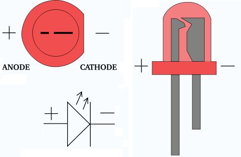
The longer leg of the LED is called the ‘anode’ and the shorter leg is called the ‘cathode’. When there is a positive voltage difference between the anode and the cathode, the LED is in forward biased or “on state” and current flows through the circuit lighting it up, otherwise the LED is in the “off state”.
Wire up the circuit shown by the following diagram. We will use the physical pin numbering in all the subsequent diagrams.
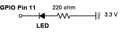
Ask an instructor or mentor is you don’t understand the diagram. For more in depth information on configuring GPIO pins as outputs refer to this website.
Now, run the 01_blinking_led.py program that is in your repo in idle. Hopefully you should have a blinking LED. If you were unsuccessful, the problem is most likely with your wiring. If you were successful reason about the correctness of the program. For example why does your program output a low voltage on pin 11 to turn the LED on and a high voltage to turn it off.
Modify the program to double the frequency at which the LED blinks. Run it to check your code.
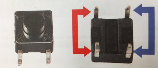
Controlling an LED using a button
Buttons are switches that are used to connect or disconnect circuits. In the figure below, pins pointed out by the arrows of the same color are internally connected. When the button is pressed, the pins pointed by the blue arrow will connect to the pins pointed by the red arrow.
In this exercise you will control an LED using a button. Your program should toggle the state of the LED everytime the button is pressed. So, if the LED is ON and the button is pressed, it should turn OFF. If the LED is OFF and the button is pressed, it should turn ON.
For the circuit you will need the following components:
- A button
- An LED (any color)
- A 220 ohm resistor
- Wires
One of the key differences in this exercise compared to the previous one is that you will configure the pin connected to the button as an INPUT pin. Here is a nice excerpt from a website explaining such a configuration:
A GPIO pin configured as an input is used to read (to input) the value of one digital signal. In this case the pin is converting the voltage being delivered to the pin into a logical value of 0 or 1 for subsequent use in the program. By convention, when the voltage on the pin is “high” (near Vcc), reading the pin will result in reading a logic 1, while when the voltage is “low” (near GND), reading the pin will result in reading a logic 0.
So, the bottom line is that when we configure a GPIO pin as an input, we can read the voltage at that pin in our Python program. But, what is the expected voltage if the pin is not connected to anything at all? The answer is that we really can’t say. When a GPIO pin is set as an input but is not connected to anything it is “floating” and has no defined voltage level. For us to be able to reliably detect whether the input is high or low we need to tie it so that it is always connected and either reads high or low.
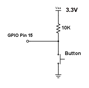
To tie the pin we connect either a Pull Up or Pull Down resistor. A Pull up resistor connects the pin to 3.3V through a large resistor, this means that when the switch is open there is a path to 3.3V and so it will read high. When the switch is pressed (with the other side connected to GND there is a lower resistance path to GND and so the pin will read low. The large (10kΩ) resistor ensures that only a little current is drawn when the switch is pressed. A pull down resistor works along the same lines (ask an instructor if you’d like to know more about pull down resistors)
Start with wiring the circuit as per the circuit diagram below:
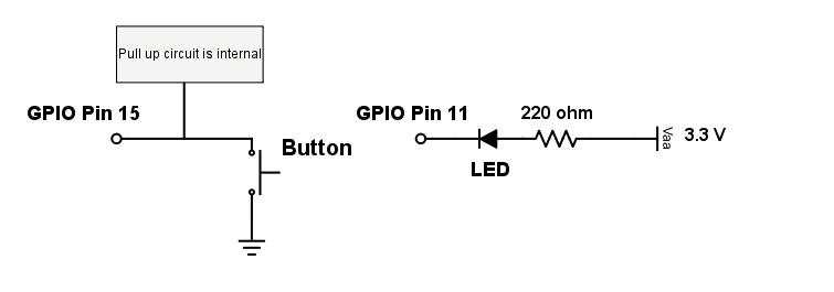
As shown above keep the LED circuit from the previous exercise. Just add another circuit that places a button between GPIO pin 15 and GND. Notice that you don’t have to wire up the pull up resistor. There is a pull up resister available internally in the raspberry Pi. We just have to specify in software that we would like to use it.
Now open the program 02_buttonLED.py in idle. This program reports the current polls pin 15 (the pin connected to the button) and reports the status of that pin: 1 indicates true or high voltage, 0 indicates False or a low voltage.
Now answer the following questions:
- Which line of code configures pin 15 to be an input pin with a pull up resistor configuration?
- Which line of code gets the status of pin 15?
- What is the purpose of the variable BtnPin?
- What do you expect the value of
buttonto be when the button in your circuit is pressed? - What should the value be when the button is not pressed?
Run the code. What do you get? Come up with a simple test to check the correctness of the program. Then modify the program to print whether the button is pressed or not pessed. You program should print “button is pressed” OR “button is not pressed” depending on the state of the button.
Finally, add logic to toggle the state of the LED (from ON to OFF or OFF to ON) everytime the button is pressed and released.
Driving a 7-segment display
A seven segment display packages seven LEDs, each LED is called a segment, which when energized forms part of a numeral. An additional eight LED is sometimes used within the same package to indicate a decimal point. By correctly energizing the individual segments of the 7-segment display you can display numbers 0 through 9.
The figure below shows the common-cathode 7-segment display:
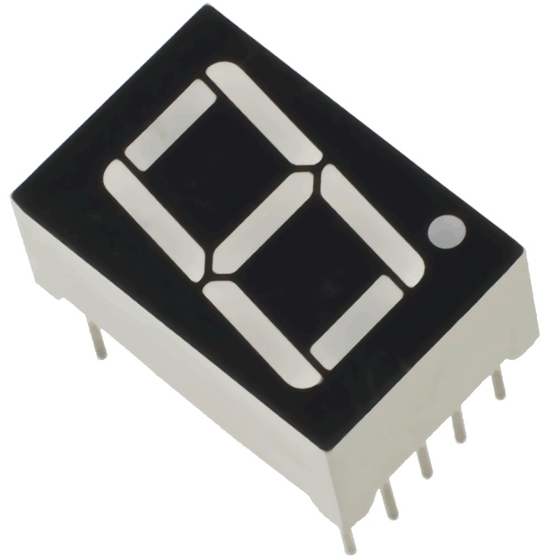
Each of the LED segments has one of its connection pins out of the package. These connection pins are labeled ‘a’ through ‘g’ representing each of the individual segments. The other pin for each LED is connected together to a common pin. In this experiment we will use a common cathod 7-segment display, which means that the all the cathodes of the LEDs are connected together to the “common pins” that are marked as zero volts in the above diagram. Each individual segment (a-g) is turned on by applying a high voltage to the corresponging pin via a current limiting resistor (forward biasing that segment). By forward biasing the appropriate pins of the LED segments, you can display any numeral value in decimal from 0 to 9.
- Draw a circuit that connects the 7 segment display to the RPi. Note that the center pins should be connected to the ground via a 220 ohm resistor. The other pins can be directed connected to the GPIO pins on the Pi.
- Once you have a drawing of your circuit get it verified by an instructor or mentor.
- Then wire your circuit.
- Create a file called
03_7seg.pyin your git repo and write a program that displays the numerals 0 - 9 in sequence then cycles back to 0. Each numeral should be displayed for 1 second. - Now combine your current circuit with the LED and button circuit from the previous exercise and modify your program to display the number of button presses so far on the 7 segment display. You can only count till 8 and have to reset back to zero once the button is pressed more than 9 times.
Congratulations on finishing lab 8!! You now have successfully built and controlled circuits via programs. We will build on this knowledge as we venture deeper into hardware and robotics!